
Earth Electrode Resistance Test (Ra) Checker
Pick the RCD rating and see the highest Ra that still meets the TT rule.
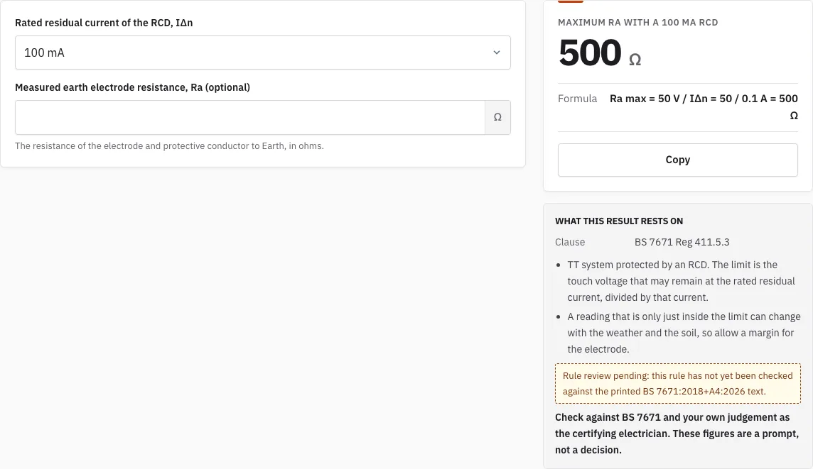
Maximum Ra with a 100 mA RCD
Ω
- Formula
- Ra max = 50 V / IΔn = 50 / 0.1 A = 500 Ω
Free · runs in your browser · nothing is uploaded
How to use the Earth Electrode Resistance Test
- Select the rated residual current of the RCD that protects the circuit. The options are 10, 30, 100, 300 and 500 mA. Use the rating physically fitted to the circuit, not the one you would like to have.
- Read the maximum Ra the page shows for that rating. This is the highest earth electrode resistance the TT rule allows for that RCD.
- If you have a measured value from an earth electrode tester, enter your Ra in the measured Ra field. Use the figure in ohms as the tester displays it. The link in the address bar keeps your entries.
- Compare the reading with the maximum shown on the page. A reading above the maximum means the earthing needs a closer look from a qualified electrician.
- Read the touch voltage the page shows. It is your Ra multiplied by the rated residual current, so it tells you what voltage your reading leaves at the RCD’s rated current.
- If you want to check the same installation against a different RCD rating, change the selection and read the new maximum. The ceiling moves a lot between ratings, so one reading can pass for one RCD and fail for another.
What is the acceptable range for earth electrode resistance?
For a TT system there is no single normal earthing resistance. The limit depends on the rated residual current of the RCD, under BS 7671 Regulation 411.5.3. Ra multiplied by the rated residual current must not exceed 50 V, so the maximum Ra is 50 V divided by that current.
The rule gives these maximums for the ratings this tool covers:
| RCD rated residual current | Maximum Ra |
|---|---|
| 10 mA | 5000 ohms |
| 30 mA | 1667 ohms (1666.7) |
| 100 mA | 500 ohms |
| 300 mA | 167 ohms (166.7) |
| 500 mA | 100 ohms |
A lower-sensitivity RCD allows a much higher Ra. A reading only just inside the limit can change with the weather and the soil, so allow a margin for the electrode rather than designing to the exact maximum.
Why is the limit different for each RCD rating?
The rule limits the voltage that can appear on exposed metalwork when an earth fault flows through the electrode. An RCD trips at its rated residual current, so the electrode only has to hold the voltage to 50 V at that current. A more sensitive RCD trips at a smaller current, which allows a higher resistance for the same voltage; a less sensitive one needs a lower resistance.
How to test earth electrode resistance?
Ra is measured with an earth electrode tester. This page does not take the reading itself, but it tells you whether the reading you get is within the limit. The fall-of-potential method is a common way to take this measurement, and the steps below follow its general pattern. Always follow the instructions supplied with your tester.
- Note the rated residual current of the RCD protecting the circuit, so you know which maximum applies before you start.
- Set up the test leads and auxiliary electrodes as the tester’s instructions describe for the fall-of-potential method.
- Take the reading on the tester and record it in ohms as Ra.
- Enter the value in the measured Ra field and compare it with the maximum for your RCD.
- If the reading is close to the limit, repeat the test at another time before you rely on it.
Every result from this page is a prompt for the certifying electrician, not a decision. Use it to decide what to check next, and let the electrician make the call.
How this tool works and where the numbers come from
The TT rule Ra x IΔn <= 50 V is Regulation 411.5.3 of BS 7671.
Sources
Frequently asked questions
What factors influence earth electrode resistance?
Moisture, dissolved salts and temperature in the soil all change its resistivity, which feeds into Ra. Electrode depth and the area of electrode in contact with the soil also matter. Deeper electrodes and greater contact area generally lower the resistance, while dry or frozen ground raises it.
How do you measure earthing resistance with a multimeter?
A standard multimeter cannot measure earthing resistance reliably, because the test needs a known current passed through auxiliary electrodes. Use an earth electrode tester for the reading. Then enter the measured Ra on this page to compare it with the maximum for your RCD rating.
What is the fall-of-potential method for measuring earth resistance?
It is a common field method. A test current is passed between the electrode under test and a remote auxiliary electrode. A voltage probe placed between them then reads the potential, and the tester works out the resistance from those readings.
What is the difference between soil resistivity and earth electrode resistance?
Soil resistivity is a property of the ground itself: the resistance of a one-cubic-metre block of soil, found with four auxiliary electrodes. Earth electrode resistance, Ra, is the resistance of your electrode and protective conductor to Earth. Ra depends on the electrode as well as the soil, which is why this page works with Ra.
Why recheck a reading that is only just inside the limit?
Soil moisture and temperature change through the year, so a reading that passed once can drift upwards. If the reading is close to the limit, repeat the test at another time before you rely on it.
Related tools
- Max Zs Calculator: use it to check the maximum earth fault loop impedance for a circuit when you are also testing its protection.
- Earth Fault Loop Impedance Calculator: use it to work out the loop impedance of a circuit from its parts.
- Maximum Zs Values for MCBs and RCBOs: use it to look up the Zs limits for common protective devices.
- RCD Test: Trip Time Checker: use it to check whether an RCD trips within its expected time.
- Prospective Fault Current Calculator: use it to estimate the fault current available at a point in the installation.
- Insulation Resistance Test: Test Voltage and Minimum: use it to find the test voltage and minimum insulation resistance for a circuit.
- EICR Codes: C1, C2, C3 and FI: use it to understand the observation codes your electrician may record on a report.