
Earth Fault Loop Impedance Calculator
Enter Ze and R1+R2 to see the Zs to expect, and compare it with what you measured.
Enter Ze and R1+R2 to see the expected Zs.
Free · runs in your browser · nothing is uploaded
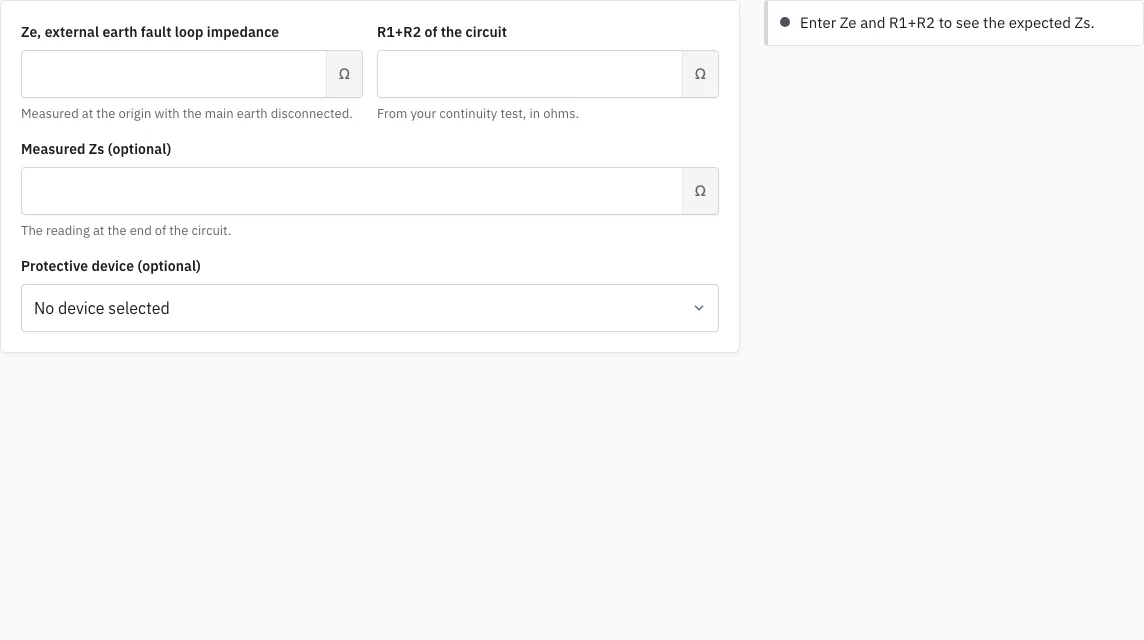
How to use the Earth Fault Loop Impedance Calculator
- Enter Ze, the external earth fault loop impedance measured at the origin of the installation.
- Enter the circuit’s R1+R2. This is the combined resistance of the line and circuit protective conductors.
- Read the expected Zs on the page. It equals Ze + (R1+R2).
- If you have a measured Zs, enter it. The page flags the reading if it does not agree with the expected value.
- Optionally, choose a protective device type (B, C or D) and a rating from 6 to 63 A. The page checks the larger of the expected and measured Zs against that device’s maximum.
The link in the address bar keeps your entries. Open that link later and the same values will be there.
Enter values in ohms exactly as your tester shows them. Leave the measured Zs empty if you have not taken it yet: the page still gives the expected value. If the page says your measured Zs does not agree with Ze plus R1+R2, first check that both were measured at the same circuit and with the same connections, then repeat the loop test before you suspect the circuit. Pick the protective device last, once you know the rating on the circuit’s breaker, so that the maximum Zs check uses the right figure.
How is earth fault loop impedance calculated?
The expected Zs is found by adding Ze to R1+R2, so Zs = Ze + (R1+R2). Ze is measured at the origin of the installation, and R1+R2 is the combined resistance of the circuit’s line and circuit protective conductors. Add the two values and you have the figure to compare with the maximum for the protective device.
The fault current travels out along the circuit’s conductors and back through the external loop, so both resistances add together. Work through it in this order:
- Measure Ze at the origin of the installation.
- Measure R1+R2 for the circuit with a continuity test, carried out under BS 7671 Chapter 64.
- Add the two values: Zs = Ze + (R1+R2).
- If you also have a measured Zs, take it from a loop impedance test under the same chapter, then compare it with the expected figure.
Worked example: Ze 0.35 ohm plus R1+R2 0.80 ohm gives an expected Zs of 1.15 ohms. For a type B 32 A device the maximum is 1.37 ohms, so this circuit sits within the limit.
Conductor resistance rises with temperature, so a Zs measured cold is lower than the circuit sees in service. Keep that in mind when a reading looks close to the limit.
What is the maximum Zs for each protective device?
Each protective device has a maximum Zs, found from 0.95 x 230 divided by (k x rating), where k is 5, 10 or 20 and the rating is in amps. The tool checks the larger of the expected and measured Zs against that maximum.
Types B, C and D use k = 5, 10 and 20 respectively. For a 32 A device, the values work out as follows:
| Device type | k | Maximum Zs at 32 A |
|---|---|---|
| B | 5 | 1.37 ohms |
| C | 10 | 0.68 ohms |
| D | 20 | 0.34 ohms |
The maximum falls as the rating rises, because the rating sits in the denominator. A result within the maximum is a prompt for the certifying electrician, not a decision.
How this tool works and where the numbers come from
Zs = Ze + (R1+R2) as used in the verification tests of BS 7671 Chapter 64; the maximum for the device is calculated from Regulation 411.4.4.
Sources
- BS 7671:2018+A4:2026 Requirements for Electrical Installations (IET Wiring Regulations): publisher page, bibliographic reference; not checked against the printed text (BS 7671:2018+A4:2026) · checked
- IEC 60228 (BS EN 60228): conductors of insulated cables, bibliographic reference for conductor resistance (Edition 4.0, published 2023-12-11) · checked
Frequently asked questions
What is earth fault loop impedance?
Earth fault loop impedance, or Zs, is the total impedance of the path a fault current takes from the supply, through the circuit, and back through the earth loop. It is made up of Ze, the external part measured at the origin, and R1+R2, the resistance of the circuit’s own conductors.
What if the earth loop impedance is too high?
If Zs is above the maximum for the protective device, a fault may produce too little current to make the device disconnect quickly, so the device may fail to operate. The tool checks the larger of the expected and measured Zs against that maximum, so an over-limit value shows up in the result.
How is the fault loop impedance test conducted?
The test confirms that the loop impedance of a circuit stays within safe limits. Under BS 7671 Chapter 64, R1+R2 is found with a continuity test and Zs with a loop impedance test. The tool takes the Ze and R1+R2 values you enter and compares them with any measured Zs.
Why does loop impedance matter?
Protective devices such as MCBs and RCBOs rely on a low enough loop impedance to cut the supply quickly when a fault happens. If Zs is too high, exposed metalwork can stay live for longer than it should. Testing shows whether each circuit keeps within the limit for its device.
Will the electricity have to be switched off?
It depends on the test. A loop impedance test is normally carried out on a live circuit, because the tester needs the supply on to measure Zs. R1+R2 comes from a continuity test, which is done with the circuit isolated.
Why does my measured Zs differ from the expected value?
The page calculates the expected Zs from Ze and R1+R2, then flags a measured Zs that does not agree with it. A difference can come from the readings themselves or from temperature, because conductor resistance rises as the cable warms. A Zs measured cold reads lower than the circuit sees in service.
Do I have to choose a protective device?
No. The device choice is optional. Without one, the page still shows the expected Zs and compares any measured value with it. Choosing a type B, C or D device with a rating from 6 to 63 A adds the maximum Zs check.
Can I keep my entries?
Yes. The link in the address bar keeps the values you entered, so you can come back to the same circuit later without typing Ze and R1+R2 again. Keep that link if you want to return to the calculation.
Related tools
- Max Zs Calculator: use it when you want to focus on the maximum Zs limit for a device.
- Maximum Zs Values for MCBs and RCBOs: use it as a reference when you need limits for a range of devices.
- Ring Final Circuit Test Calculator: use it when the R1+R2 figure comes from a ring final circuit.
- RCD Test: Trip Time Checker: use it when the circuit is protected by an RCD and you need to check trip times.
- Prospective Fault Current Calculator: use it when you need the fault current a circuit could deliver.
- Earth Electrode Resistance (Ra) Checker: use it when you are checking the earth electrode rather than the fault loop.