
R1+R2 Calculator
Enter the cable length and sizes to see the R1+R2 reading to expect, and compare it with what you measured.
Enter the cable length to see the estimate.
Free · runs in your browser · nothing is uploaded
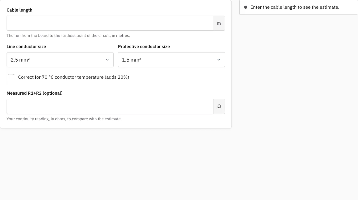
How to use the R1+R2 calculator
- Enter the length of the circuit in metres, from the origin to the furthest point. Use the length of the cable run, not the straight-line distance between the two ends.
- Choose the size of the line conductor in mm², from 1 to 35.
- Choose the size of the protective conductor in the same way. For a twin and earth cable this is the smaller earth conductor, not the same size as the line.
- Tick the 70 °C box if you want the estimate for a conductor at working temperature; the page adds 20 percent.
- Read the expected R1+R2 and the formula under it.
- If you have already measured the circuit, type your reading to compare it with the estimate. The page says whether it agrees or differs, and by how much.
The link in the address bar keeps your entries, so you can send the same case to a colleague. Take the length from the drawings or by measuring the cable route, and add a little for the drops to accessories, because the estimate follows the length you give it. Remember that the estimate is for one radial run. A ring final circuit follows a different method, which the ring final circuit test page covers.
How is R1+R2 estimated?
R1+R2 is the resistance of the line conductor plus the resistance of the circuit protective conductor, measured from the origin of the circuit to the point being tested. The page works it out as the length multiplied by the resistance per metre of the line and the protective conductor, divided by 1000 because the values are given in milliohms per metre. The resistance per metre for each size comes from the conductor standard IEC 60228, for plain copper conductors at 20 °C, and the page shows that source under every result.
Take a circuit of 20 m wired with a 2.5 mm² line conductor and a 1.5 mm² protective conductor. The formula is 20 m × (7.41 + 12.1) mΩ/m / 1000, which gives 0.390 ohm. With the 70 °C box ticked, the same circuit gives 0.468 ohm, because the page multiplies by 1.20. A 10 m run with a 1 mm² line and a 1 mm² protective conductor gives 0.362 ohm.
| Circuit | Estimate |
|---|---|
| 20 m, 2.5 mm² line, 1.5 mm² protective conductor, 20 °C | 0.390 ohm |
| Same circuit with the 70 °C correction | 0.468 ohm |
| 10 m, 1 mm² line, 1 mm² protective conductor | 0.362 ohm |
What does the comparison with my reading show?
The page treats a reading as agreeing when it lies within 10 percent of the estimate or within 0.05 ohm, whichever is larger. A reading outside that range is flagged, with the difference in ohms. A difference does not tell you what is wrong. It is a prompt to check the length you entered, the conductor sizes, the connections and the zero of the tester, and then to measure again. The result is a prompt for the person certifying the work, not a decision.
Why is the estimate different from my reading?
Real cable is rarely exactly the data-sheet size, joints and terminations add a little resistance, and the length is often only approximate. For these reasons the estimate is a guide to the size of the reading, not a limit. The limits that matter for the circuit are the maximum earth fault loop impedance and the other test limits on the related pages.
How this tool works and where the numbers come from
R1+R2 is the length times the resistance per metre of the line and protective conductors; the resistance values are those of the copper conductor standard (IEC 60228), shown with their source.
Sources
- BS 7671:2018+A4:2026 Requirements for Electrical Installations (IET Wiring Regulations): publisher page, bibliographic reference; not checked against the printed text (BS 7671:2018+A4:2026) · checked
- IEC 60228 (BS EN 60228): conductors of insulated cables, bibliographic reference for conductor resistance (Edition 4.0, published 2023-12-11) · checked
Frequently asked questions
What do R1 and R2 mean?
R1 is the resistance of the line conductor and R2 is the resistance of the circuit protective conductor. Their sum, R1+R2, is the resistance of the earth fault loop inside the circuit, and it is the value you measure when you test continuity.
Can I use the calculator for a ring final circuit?
No. A ring final circuit is measured end to end and the expected value is worked out in a different way. Use the ring final circuit test page for that, which works out the value as (r1 + r2) / 4.
Why should I add the 70 °C correction?
Resistance rises with temperature, and the standard values are for 20 °C. The 20 percent correction shows the value at the maximum working temperature of the conductor. Leave it off if you want to compare with a reading taken on a cold circuit.
How can I use R1+R2 to get Zs?
Add the external earth fault loop impedance, Ze, to R1+R2. The earth fault loop impedance calculator does that for you and compares the result with the maximum for the protective device.
Does the page store my numbers?
No. The calculation runs in your browser. The values stay in the link in the address bar, which only you and the people you send it to can see.
Related tools
- Earth Fault Loop Impedance Calculator: use it to add Ze to R1+R2 and compare with a measured Zs.
- Ring Final Circuit Test: use it for the end-to-end readings of a ring.
- Max Zs Calculator: use it to compare a measured Zs with the maximum for the protective device.
- Maximum Zs Values for MCBs and RCBOs: use it to look up the maximum Zs for each rating.
- Insulation Resistance Test: Test Voltage and Minimum: use it for the insulation test of the same circuit.
- Schedule of Test Results: use it to record the readings with the rest of the circuit.
- EICR Certificate Maker: use it to put the results into a condition report.