
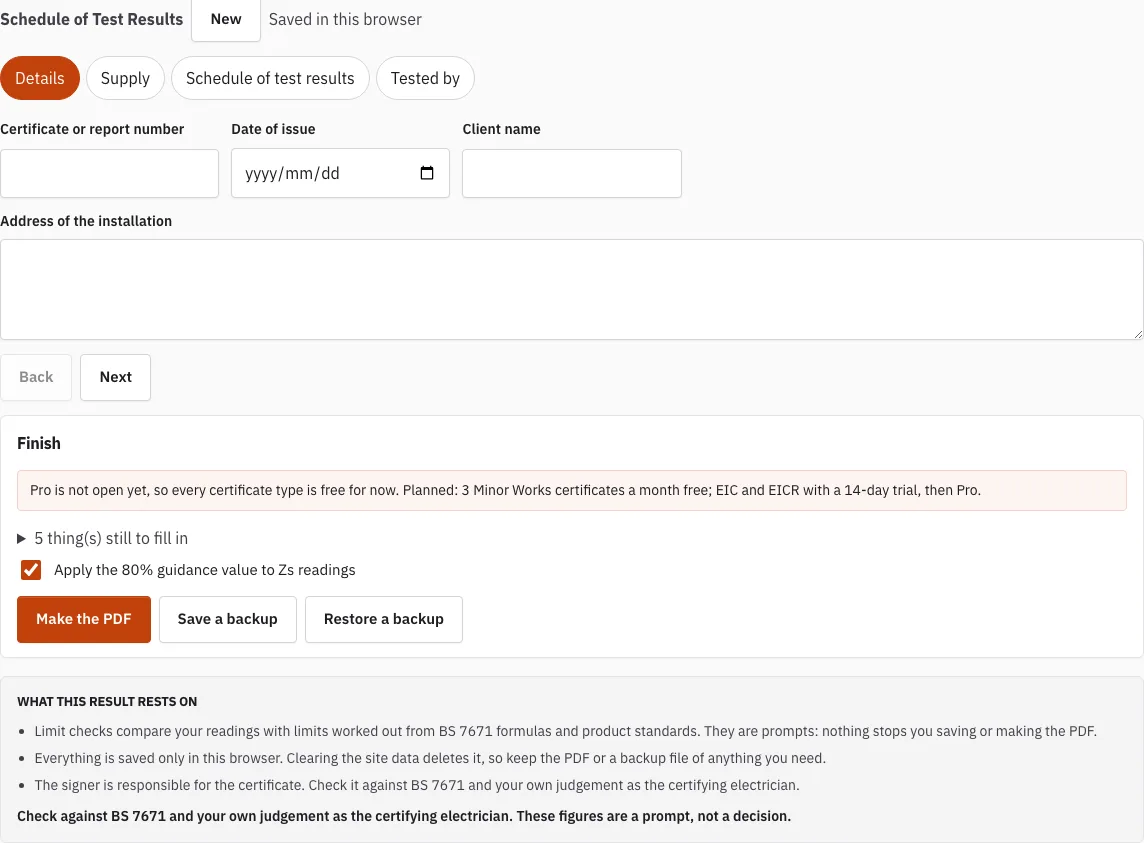
Schedule of Test Results
Enter your circuit test results and see each reading checked against its limit.
Saved in this browser
Nothing saved in this browser yet.
Finish
Free plan.
5 thing(s) still to fill in
- Client name
- Address of the installation
- Earthing arrangement
- At least one circuit in the schedule of test results
- Signature: inspector
Free · runs in your browser · nothing is uploaded
How to use the Schedule of Test Results
- Fill in the details and the supply section: earthing arrangement, nominal voltage to earth Uo, prospective fault current and Ze.
- Click “Add a circuit” to create a panel for each circuit.
- Enter the circuit number, description, type of wiring, reference method, number of points and conductor sizes.
- Choose the protective device standard, type, rating and short-circuit capacity. For a fuse, type in the maximum Zs from the device data.
- If the circuit has an RCD, choose the RCD type and enter the trip times at 1 x and 5 x IΔn.
- For a ring, set the circuit type to “Ring final” and enter r1, rn and r2.
- Enter R1+R2, Zs, the insulation test voltage and resistance, polarity and the AFDD test button result.
- Read the status line under each circuit and deal with anything flagged.
- Click “Add a board” for each further distribution board, and enter its reference, location, Zs, prospective fault current and surge protective device field.
- Complete the “tested by” signature.
“Copy this circuit” duplicates a row and “Delete this circuit” removes it. The table at the top lists your circuits with a check count. Entries are saved in this browser, so use “Save a backup” to keep a file copy and “Restore a backup” to load it again.
What Is the Schedule of Test Results?
The schedule of test results is the record of measured readings for each circuit, kept with the certificate for an installation. It holds what the electrician measured, such as continuity, earth fault loop impedance and insulation resistance, so anyone reviewing the work can see what was found. This tool sets that record out circuit by circuit.
BS 7671 provides the model layouts for these schedules. The readings belong beside the circuit details they relate to, which is why each circuit here has its own panel.
What Goes on Each Schedule?
Each circuit panel holds five groups of fields. Ring readings only appear when the circuit type is set to ring final.
| Group | Fields |
|---|---|
| Circuit details | Circuit number, description, type of wiring, reference method, number of points, live and protective conductor sizes |
| Protective device | Standard, type, rating, short-circuit capacity, maximum disconnection time |
| RCD | RCD type, rated residual current, trip times at 1 x and 5 x IΔn |
| Ring final (ring circuits only) | r1, rn and r2 |
| Test results | R1+R2, Zs, insulation test voltage and resistance, polarity, AFDD test button |
Which readings are checked?
Zs, insulation resistance, RCD trip times, ring final readings and device short-circuit capacity are checked as you type; for a ring circuit, R1+R2 is compared with (r1 + r2) / 4. The two that need most care are below.
How does it check Zs?
The tool compares your measured Zs with the maximum allowed for the protective device. For a type B, C or D MCB or RCBO, the maximum is worked out as 0.95 x 230 V divided by the instantaneous trip current, which is 5, 10 or 20 times the rating. For a fuse, you type in the maximum Zs from the device data yourself.
Check the device type and rating before you read the result, because the limit depends on both. You can look up limits in the Maximum Zs Values for MCBs and RCBOs guide. Where a rule has not yet been checked against the printed BS 7671:2018+A4:2026 text, the status line says “rule review pending”.
What about RCD tests?
For an RCD circuit, the tool records the trip time at 1 x IΔn and at 5 x IΔn and checks each one against the product-standard limit. The 1 x test applies the rated residual current; the 5 x test applies five times that current and is made on RCDs of 30 mA or less that give additional protection. A general RCD must trip within 300 ms at 1 x and 40 ms at 5 x; the limits for an S type are different, and the RCD test page lists them.
A flagged trip time is a reason to check the device and retest before you sign, not a decision the tool makes for you.
How this tool works and where the numbers come from
Limits come from the formulas and values in BS 7671 with the regulation number shown; where a rule is not yet checked against the printed book the row says so.
Sources
Frequently asked questions
What is R1+R2 on the schedule?
R1+R2 is the combined resistance of the line conductor (R1) and the circuit protective conductor (R2). It is measured to confirm the earth path is continuous, and you enter it in the test results part of each circuit panel.
Can I record ring final circuits?
Yes. Set the circuit type to “Ring final” and the r1, rn and r2 fields appear. The tool checks (r1 + r2) / 4 against the R1+R2 you entered, so record both sets of readings.
Is this the BS 7671 schedule itself?
No. BS 7671 has model forms in Appendix 6; this is a working record in our own layout for the same kind of readings. You fill it in on site and save the PDF when the work is done.
What is the minimum insulation resistance?
BS 7671 gives 1 MΩ as the minimum, measured with a 500 V d.c. test for circuits up to and including 500 V, other than SELV and PELV. The tool checks each insulation reading against the minimum for the circuit voltage.
Do I need to fill every box in the schedule?
No, but a blank needs a reason. If a field does not apply, or the testing was limited, say so in the remarks rather than leaving it empty, so the reader knows it was not forgotten.
How do I see which readings are checked?
Each circuit panel shows a status line for every reading the tool can check: Zs against the maximum for the device, insulation resistance, RCD trip times, ring final readings and short-circuit capacity against the prospective fault current. Readings outside a limit are marked with an asterisk in the PDF and listed under the table.
Related tools
- EICR Certificate Maker: use it for the periodic inspection report that goes with these readings.
- Electrical Installation Certificate (EIC): use it for new installation work.
- Minor Works Certificate: use it for small additions or alterations.
- EICR Certificate Template: a starting layout if you want to lay out an EICR by hand.
- Minor Works Certificate Template: a starting layout for minor works paperwork.
- Which Electrical Certificate Do I Need?: check this first if you are unsure which form fits the job.
- EICR Codes: C1, C2, C3 and FI: use these to classify the findings you record.
- Maximum Zs Values for MCBs and RCBOs: look up the limit before you type in a Zs reading.